As with flatness, there are two types of straightness control. Where a straightness is applied to a size dimension, it is controlling the feature’s derived median line or derived median points. Where the straightness control is applied to the surface of a feature, it controls straight lines in the surface.
Drawing shows both types of straightness on an axonometric view. Where the straightness tolerance is applied to the size dimension it overrides Rule #1. Where straightness is applied to lines in the surface of a regular feature of size, it is refining the straightness provided by Rule #1 and must be less than the total size tolerance.

On the drawing above straightness is applied to the surface of a cylindrical feature. In this case the straightness tolerance must always be less than the size tolerance.
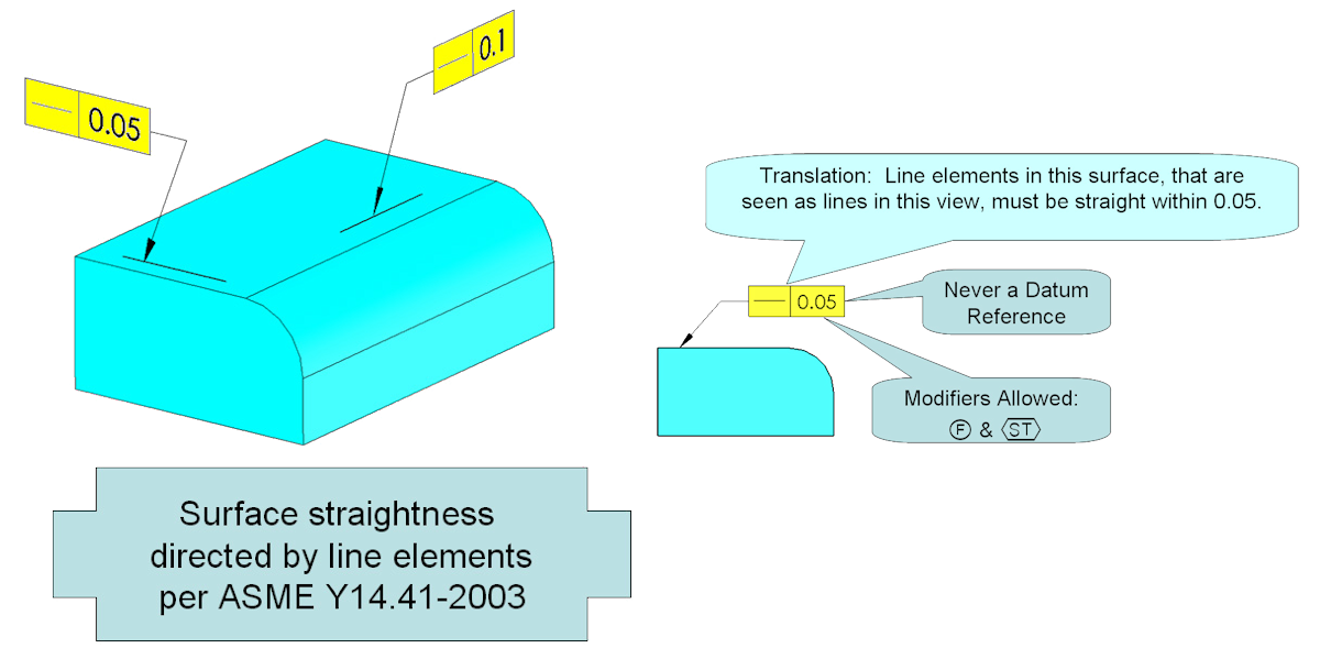
It is necessary to indicate the direction of the line elements being controlled. In Y14.5 this is determined by the view the straightness control is in. In the Digital Modeling standard Y14.41 the direction may be indicated by a directed line. Here two different straightness controls have been applied to the same surface but in different directions.
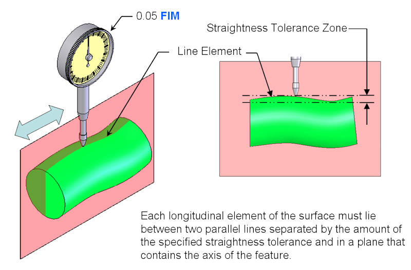
Surface straightness may be applied to any surface that contains straight line elements. The tolerance zone is 2-dimensional. Where applied as a surface control, straightness cannot be modified at MMC or LMC. Often surface controls are inspected using an indicator. The full indicator movement (FIM) may not exceed the tolerance stated in the feature control frame for any line element of the surface. Because there is never a datum reference on a straightness control, the part must float to find the lowest possible FIM for each line element.

Used to control line elements in one direction better than the control provided by:
- flatness
- cylindricity
- a size tolerance
- perpendicularity
- parallelism
- angularity
- profile of a surface
- total runout