Watch the Placement of Datum Identification Symbols and the Feature Control Frames for Straightness, Perpendicularity, Parallelism and Angularity - 2009 (#15A)
(In accordance with the ASME Y14.5-2009 standard)
PDF is Available with GD&T Reference Center Subscription.
When applying the above to features of size, the placement of the feature control frame can greatly change the meaning. If the feature control frame is associated with the size dimension, the feature’s axis or center plane is being identified or controlled. If the feature control frame is associated with the surface of the feature of size, it is identifying or controlling the surface – not the axis or center plane.
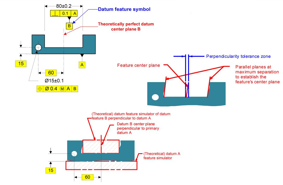
In this example both the datum feature symbol and the perpendicularity apply to the feature’s center plane. In this case, the Ø15 hole is located to the center plane.

First, verify datum feature B (center plane) perpendicularity requirement.
Second, establish datum reference frame A primary, B secondary to verify Ø15 hole location.
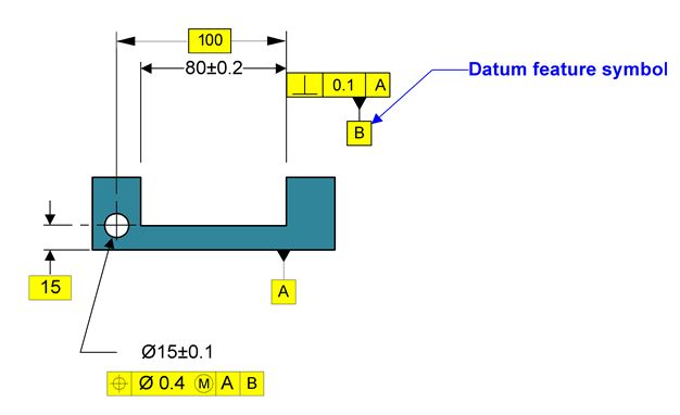
In the second example, both the datum feature symbol and the perpendicularity apply to the right surface of the slot.

In this case, the Ø15 hole is located to the right surface of the slot.
First, verify datum feature B (surface) perpendicularity requirement.
Second, establish datum reference frame A primary, B secondary to verify Ø15 hole location.
NOTE: The datum symbol location has the same rules in the 1994, 2009 & 2018 standards, but the terminology regarding datum simulators is different in the 2009 standard.
This tip is in accordance with ASME Y14.5-2009.
This tip was originally released in August 1998.

