Use Profile to Open up Your Tolerances - 2018 (#47C)
(In accordance with the ASME Y14.5-2018 standard)
PDF is Available with GD&T Reference Center Subscription.
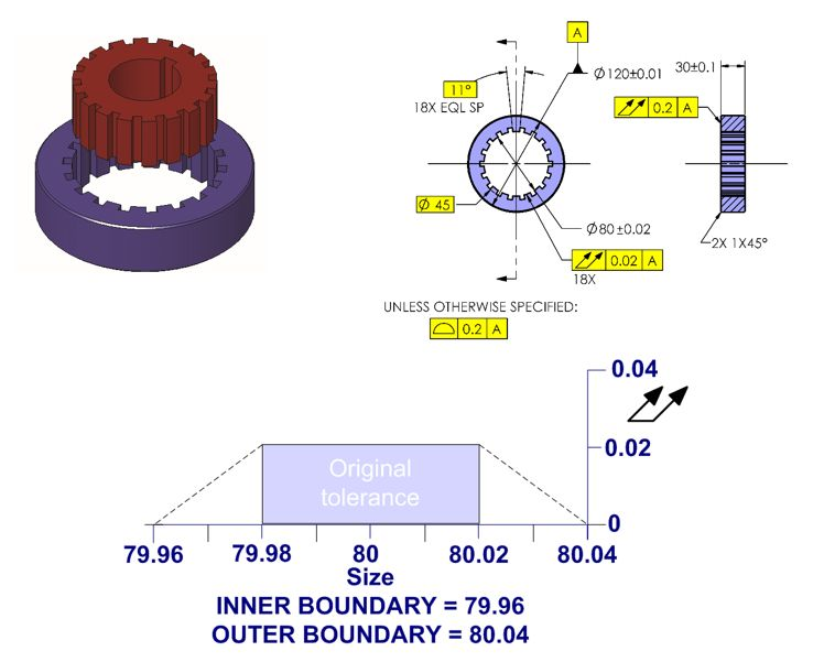
Profile of a surface is the most versatile yet one of the least used of the geometric tolerances. The next few tips will illustrate some of the power of profile of a surface. On the part shown below, the 18 teeth must be controlled to assure that the teeth do not interfere with the mating part and make certain that the clearance between the parts is not too great. Originally, the part was controlled using a tight size tolerance and a total runout tolerance. The real concern here is that the inner and outer boundaries are not exceeded. Using the original approach, the inner and outer boundaries are 79.96 and 80.04 respectively. This is illustrated in the dynamic tolerancing diagram chart.

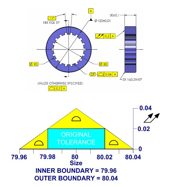
By making the size dimension basic and applying a profile of a surface tolerance of 0.04, more parts will be accepted while not violating the inner and outer boundaries. On the chart below, the crosshatched rectangular area shows the range of acceptable parts based on the original drawing. The double crosshatched triangular areas indicate the additional tolerance allowed by profile of a surface. Notice that the inner and outer boundaries required for this part to function did not change. The tolerance has essentially doubled by switching to profile of a surface. In this actual application, the supplier was not able to meet the required process capability (Cpk) using the original drawing. After making the drawing change, the vendor had no problem delivering acceptable parts to the required Cpk.
Notice that we also added a CF symbol in place of the quantity symbol. This concept is new in the 2018 standard. It allows the "CF" symbol to be applied to the 18 surfaces to create a continuous feature.

This tip is in accordance with ASME Y14.5-2018.
This tip was originally released in September 2001.
