Patterns of Features Used to Establish a Datum Part 3 of 3 (#68-3)
(In accordance with the ASME Y14.5-2018 standard)
(In accordance with the ASME Y14.5-2009 standard)
PDF is Available with GD&T Reference Center Subscription.

For our example part, the Housing, we will clarify why using the pattern of two holes as datum feature B really isn’t needed if datum feature B is referenced at MMB. The result would be the same if one hole is datum feature B, at MMB, and the other is datum feature C, at MMB. In fact, we will show that only datum feature A may be required, with the same outcome that would be obtained by specifying the datum reference frame [A,B] or [A,B,C], with tolerances specified at MMC, and datum features referenced at MMB.
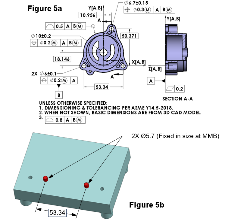
Figure 5a) The Housing with the same two-hole pattern as datum feature B, but now specified at MMB
The MMB modifier that follows each datum feature B reference is an instruction, requiring that datum feature simulator B will be fixed in size at the MMB. The datum feature simulator will differ from the RMB case, shown in tip #68 only by having fixed size pins as the datum feature B simulator. The MMB for the two datum feature B holes is Ø6 – 0.1 – 0.2 = Ø5.7 mm.
Figure 5b shows the datum feature simulator set for this example.
Figure 5b) Datum feature simulator set for datum feature B referenced at MMB

- If the two holes in the pattern (datum feature B) have better than their worst-case size, orientation, or relative location, then some looseness of fit with the simulators will allow shift between the part and datum reference frame.
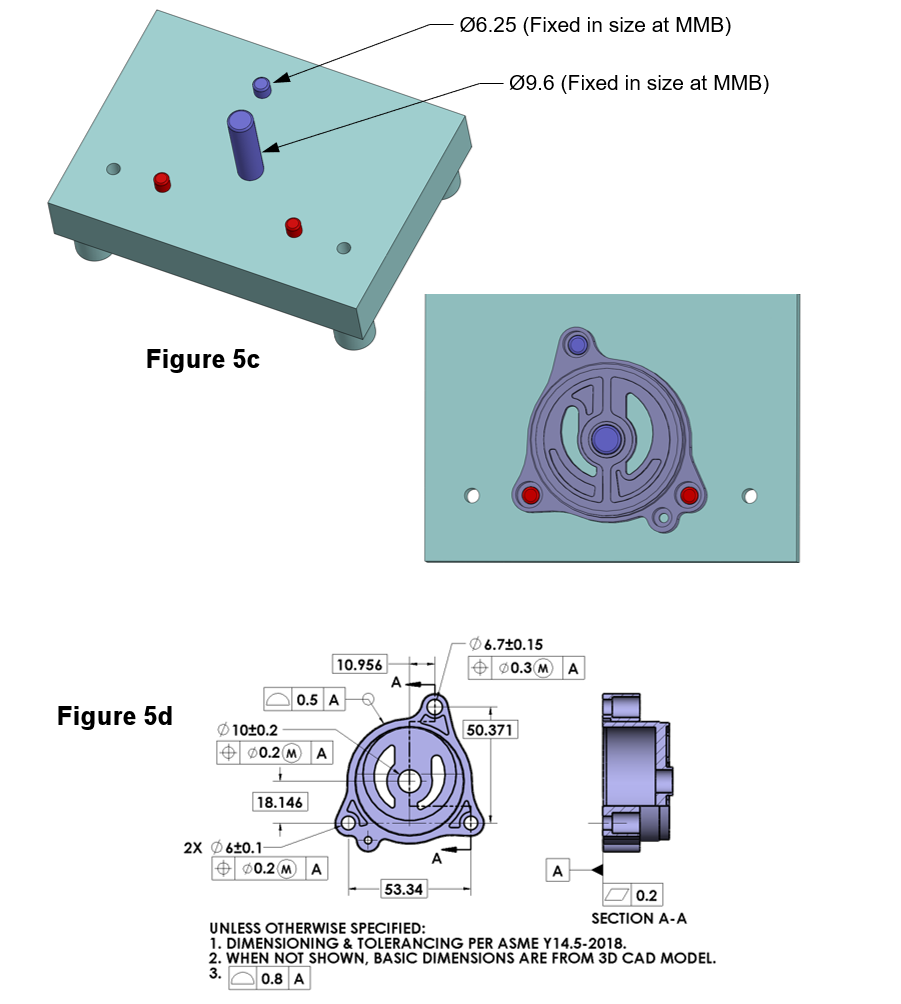
- Since the pins are fixed in size, when the Housing is placed on the datum feature simulators it fits the same, whether datum feature B is a pattern of two holes, or one hole is datum feature B and the other is datum feature C, the part to simulator relationship is unchanged. We can take this one step further. See Figure 5c.
In Figure 5c additional pins are added at the Virtual Condition (VC) size of several of the other features on the Housing. The datum feature simulator set has been made into a functional go-gage. If the two Ø6 mm holes, and all of the other features that are toleranced at MMC relative to the datum reference frame [A,B] do not violate their maximum material boundaries, then the part will go onto the gage. If local sizes for all the features are also within spec, then no further inspection may be needed.
Figure 5c) A functional gage for many features on the Housing:

- Pins are now added to create a functional gage for the Housing.
- One Pin is at the Virtual Condition (VC) size for the 3rd mounting hole.
VC = Ø6.7 – 0.15 – 0.3 = Ø6.25 - One Pin at the VC size for the center hole.
VC = Ø10 – 0.2 – 0.2 = Ø9.6
If the part fits on the functional gage, and all local sizes for the four holes are within the limits of size, then these features are conforming to the size and position tolerances. This is using the surface method of evaluation of the position tolerances that are specified at MMC.
Figure 5c shows us that it doesn’t matter which features are datum features and which are toleranced relative to them. As far as the gage is concerned, all the features are the same. From a design and function point of view, with the same effect as for the specs in Figure 5a, we can instead specify the tolerances as shown in Figure 5d.
Figure 5d) The Housing with all tolerances referencing only datum feature A
The rule of simultaneous requirements ties all tolerances referencing datum feature A together. Since they must be met simultaneously, all feature to feature basic dimensions apply to each of the tolerances.
The functional gage shown in Figure 5c applies directly to the specifications shown here.
This tip is in accordance with ASME Y14.5-2009 and ASME Y14.5-2018
This tip was originally released, in accordance with ASME Y14.5M-1994, in July 2003.
