Watch placement of datum triangles in the latest Standard - 1994, 2009, 2018 (#17)
(In accordance with the ASME Y14.5-2018 standard)
(In accordance with the ASME Y14.5-2009 standard)
(In accordance with Y14.5M-1994 standard)
PDF is Available with GD&T Reference Center Subscription.
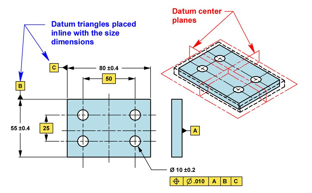
A subtle difference in the placement of the datum triangle can drastically affect the drawing’s meaning. The first drawing illustrates establishing datum center planes for datums B and C. To do this, the triangles are placed inline with the size dimensions. This approach would be used if the pattern of holes should remain centered on the plate regardless of the actual length and width.
If the centering of the pattern of holes is not important, the datum triangles may be offset as shown in the following drawing. Datum planes are established by the sides of the part. Although, this approach is usually preferred by manufacturing, the symmetry of the part is lost and may cause confusion at inspection. Depending on the actual size of the part, the pattern will be controlled better to one side than the other.

This tip is in accordance with ASME Y14.5M-2994, ASME Y14.5-2009 and ASME Y14.5-2018.
This tip was originally released in October 1998.