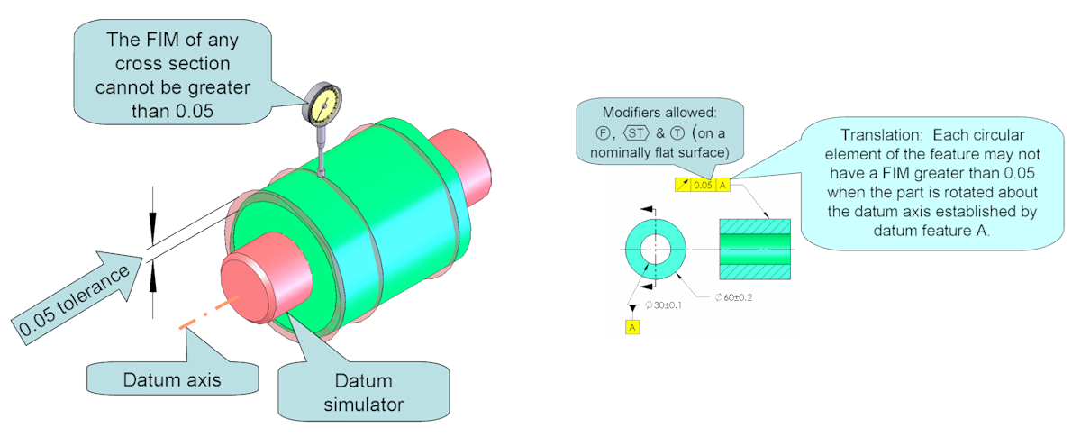
Circular runout applies to individual cross-sections. No cross-section or circular element in the surface may have a full indicator movement (FIM) of more than 0.05.
Circular runout tolerance zones for cylindrical features are now defined as 2 circles coaxial to each other and the datum axis, as well as normal to the datum axis. The distance between the circles is the tolerance value and is in the direction normal to the surface. The circles are allowed to change size (within the limits of size) as long as the distance between them is maintained. The tolerance zone applies independently to all cross sections of the feature.
Where applied to a surface which is perpendicular to the datum axis, circular runout controls wobble but not location.

Note: The way to describe both circular and total runout changed in the 2018 Standard. Previous standards described the runout tolerance zones in terms of full indicator movement (FIM) of a dial indicator placed on the surface of the feature as the part is rotated 360° about the datum axis. However, the Y14.5 standard is not an inspection standard, so the use of inspection equipment was removed. Tolerance zones are now defined geometrically and not as a function of the inspection method. In our examples, we will show both methods. While the description of the tolerance zones have been modified, the effective tolerance zones and how the runout controls are used have NOT changed. Descriptions of tolerance zones depend on the type of feature being controlled. We will look at each different type: cylindrical features, planar features and non-cylindrical and non-planar features.
