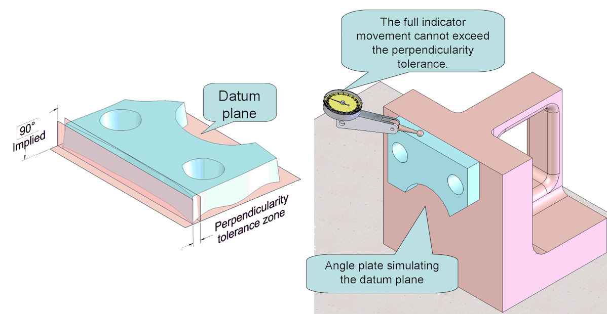
The perpendicularity tolerance applied to a flat surface is specified by placing the feature control frame on an extension or leader line.

In this case, the tolerance zone is a pair of parallel planes 0.1 mm apart. The tolerance zone is perfectly perpendicular to the datum plane A. The tolerance zone may be thought of as a flatness tolerance zone that is oriented at exactly 90 degrees to the datum.
Where perpendicularity is applied to a size dimension, the tolerance applies to the axis or center plane of the feature of size. Because it is associated with a feature of size, the MMC and LMC modifiers are allowed. Perpendicularity is usually used to control a secondary or tertiary datum feature to higher precedent datums. The perpendicularity tolerance zone is at 90° to the datum plane(s) or axis. It may be used to control the perpendicularity of a feature better than the control provided by:
- position
- profile of a surface